Solax
Supported Devices
| Device Type | Modbus TCP (Ethernet) | RS485 | Curtailment | Minimum device firmware version |
|---|---|---|---|---|
| Solax X1 Hybrid G4 | ✅ | ✅ | ✅ | |
| Solax X3 Hybrid G4 | ||||
| Solax X3 Ultra | ARM 026.01-000.09 | DSP 025.04 | Module 1.007.02 | |||
| Solax X3 IES | ||||
| Solax ESS-TRENE | ||||
| Solax ESS-AELIO |
Installation
For the Solax X3 Hybrid G4 please make sure that the inverter has the latest firmware version installed.
Connection methods
- SolaX G2, SolaX G3 Hybrids, Solax ESS (TRENE and AELIO) have built in Ethernet (The Qcells Q.VOLT HYB-G3-3P is a SolaX G4 despite the G3 naming).
- SolaX G4 and other don't have built-in Ethernet, communication is possible via serial RS485 COM port.
The RS485 interface uses only the pin4 (blue wire) and pin5 (white-blue). Polarity matters, so make sure pin4 (blue wire in typical cables) is connected to the A lead of your adapter and pin5 (white-blue wire) to the B lead of your adapter.
RS485 cables can be fairly long, so 25 meter or more is possible. You can use the blue pair of a standard cat5 or cat6 cable.
Make sure you verify your inverter's baud rate with the (115200) and make sure it matches the baud rate of the Ethernet to RS485 adapter You can confirm the baud rate on the LCD screen on the front of your Inverter, within the Menu's.
The Modbus address be default is 1. Some people have reported that their Modbus address was 4.
There is a port marked COM on the G4 inverter, some user manuals by mistake claim that this is an Ethernet port.
DO NOT CONNECT THIS COM PORT TO AN ETHERNET SWITCH - your Ethernet switch port will die if you do!!!
RS485 to ETH
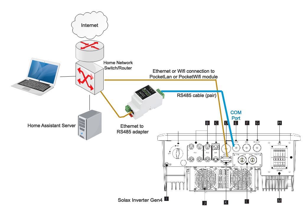
- connects through Ethernet to your home network router/switch
When configuring the SolaX Modbus integration, specify the network IP address of the converter device, not the address of the SolaX. Do not tick the Serial RS485 flag; the serial port is ignored in this setup.
Multiple inverters connected to one RS485 adaptor & Terminating resistors�
It should be possible to connect multiple inverters to the same RS485 adapter (eg Waveshare). The inverters must have different Modbus addresses, so you need to change the Modbus addresses of the inverters first. Then configure one instance for each inverter. The configuration dialogue allows you to set the Modbus address.
The use of Terminating resistors is required when connecting multiple Inverters. Place a 120Ohm resistor accross A&B at the RS485 adaptor and place a 120Ohm resistor accross A&B on the last connected Inverter.