Okablowanie Autarco LH-series RS485
Ta strona opisuje komunikację z hybrydowym inwerterem serii Autarco LH przez Modbus-RTU (rs485). Domyślnie inwerter jest ustawiony na adres 1. Interfejs RS485 to 4-pinowy złącze zwane "COM", znajdujące się na dolnej części inwertera za osłoną ochronną. Dokładna pozycja jest oznaczona w pomarańczowym prostokącie na poniższym obrazku:
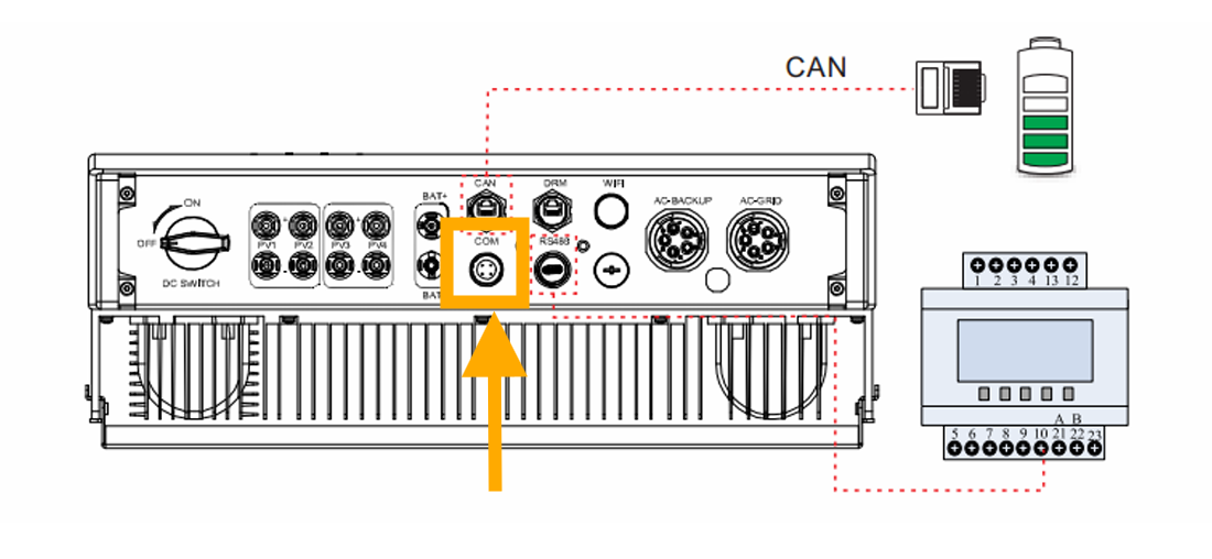
Z bliska port wygląda tak:

Do tego 4-pinowego złącza na inwerterze Autarco należy użyć odpowiedniego złącza, aby podłączyć do Sofar EMS. Na Sofar EMS, inwerter można podłączyć do portu RS485. Okablowanie jest następujące:
RS485 Wiring
- For correct RS485 wiring: Follow the guidelines for RS485 wiring.
- If the wiring shown in the table below is incorrect, please let us know.
- There is no general consensus in the industry about the usage of A and B for the RS485 polarity, so it may be counterintuitive and opposite of what you might expect for some devices.
| Device | Sofar EMS model OM1 | Sofar EMS model IG8 | RS485-USB converter | RS485-Ethernet converter |
|---|---|---|---|---|
| Pin 3 | RS485 A | RS485_POS | RS485 A | TX+ |
| Pin 4 | RS485 B | RS485_NEG | RS485 B | TX- |
| N/A | RS GND | GND | Not available | G |
NOTE: RS485 Device Addresses
- You MUST give each device on the RS485 bus a unique address. Check the manual of the device on how to do this.
- Use lower addresses first (1, 2, ...) because the Sofar EMS will find them faster!
- For each device, it is generally recommended to stick with the factory default baud rate, parity, and stop bits. The Sofar EMS will scan on those first.