
The insulation class of the cables must be suitable for the intended signal voltage. Ensure that the cables used comply with the appropriate safety and operational standards for the specific voltage levels in the system.
The following guidelines apply:
For places in residential settings that have no ethernet cabling installed, you may consider Powerline adapters. Please note that only wall sockets that are on the same phase can be used with most powerline adapters.
All Sofar models are extendible with additionaly I/O's through the accessories. See accessories for more information.
The permissible wire cross-section for the connectors is as follows:
| Type | Section (AWG) | Section (mm²) |
|---|---|---|
| Solid Wires | 26-16 AWG | 0,129-1,31 |
| Stranded (Flexible) Wires | 26-16 AWG | 0,129-1,31 |
You MUST respect the voltage & current ratings from the Specifications. Using the device outside of its rated values is dangerous and may lead to damage and injuries.
| Interface | Voltage (V) | Current (A) |
|---|---|---|
| Relay | Max. 30Vac / 50Vdc | 1.0 A |
| Digital input | 5-50Vdc | N/A |
If you need the switch higher voltages or currents than what the relay is rated for, then use the relay of the Sofar EMS to switch another relay that has the voltage or current rating that you need.
The following guidelines apply:
Scenario 1 (left example): Active Meter (Voltage Output) Use this wiring if the meter generates its own voltage pulse.
Scenario 2 (right example): Passive Meter (Dry Contact) Use this wiring if the meter acts as a relay/switch. The controller provides the wetting voltage (12V).
The color of the wires does not matter. You may choose this, as long as both the A and B are from a single twisted pair.
The following guidelines apply:
Different manufacturers use different naming conventions (A/B, +/-, D1/D0). Use this table to match your device's signals to the Sofar controller.
| Device | Sofar EMS model OM1 | Sofar EMS model IG8 | RS485-USB converter | RS485-Ethernet converter |
|---|---|---|---|---|
| RS485 A | RS485_POS | RS485 A | TX+ | |
| RS485 B | RS485_NEG | RS485 B | TX- | |
| RS GND | GND | Not available | G |
Grounding shielded cables
To the left of the I/O connections on the Sofar EMS, there are three DIP switches for terminating and biasing the RS485 communication bus.
The correct configuration depends on the topology of the RS485 bus. In most cases, activating all resistors is the recommended choice. Do this if you are unsure. This is different if the Sofar EMS is not at the end of the communication bus or if another device has active bias resistors.
Whether the resistors are active or not depends on the position of the DIP switches. To do this, you need to consider the production date of the Sofar EMS. You can deduce this from the serial number. The serial number starts with production code OM1, followed by six digits representing the production date. E.g. OM1240315 was produced on 15/03/2024.
If your is manufactured before 1 August 2024: (These devices have white switches coming from a black component).
If your is manufactured after 1 August 2024: (These devices have white switches coming from a red component).
You MUST give each device on the RS485 bus a unique address.
Use lower addresses first (1, 2, ...), because the Sofar EMS will find them faster!
Stick with the factory default baud rate, parity and stop bits. The Sofar EMS will scan on those first.
The permissible wire cross-section for the connectors is as follows:
| Type | Section (AWG) | Section (mm²) |
|---|---|---|
| Solid Wires | 26-18 AWG | 0,129-1 |
| Stranded (Flexible) Wires | 26-18 AWG | 0,129-1 |
The color of the wires does not matter. You may choose this, as long as both the A and B are from a single twisted pair.
The following guidelines apply:
Different manufacturers use different naming conventions (A/B, +/-, D1/D0). Use this table to match your device's signals to the Sofar controller.
| Device | Sofar EMS model OM1 | Sofar EMS model IG8 | RS485-USB converter | RS485-Ethernet converter |
|---|---|---|---|---|
| RS485 A | RS485_POS | RS485 A | TX+ | |
| RS485 B | RS485_NEG | RS485 B | TX- | |
| RS GND | GND | Not available | G |
TIP: In case of many devices
Grounding shielded cables
Multiple ports Do not connect the same RS485 bus to multiple ports on the Sofar. This will introduce interference.
You must install 120 ohm termination resistors on both ends of the serial communication bus. The Sofar does not have an integrated termination resistor.
You MUST give each device on the RS485 bus a unique address.
Use lower addresses first (1, 2, ...), because the Sofar EMS will find them faster!
Stick with the factory default baud rate, parity and stop bits. The Sofar EMS will scan on those first.
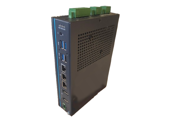
The Ultra has three ethernet ports, labelled A, B and C on the enclosure. Port A is 2.5 gigabit, ports B and C are gigabit.
All three ports are bridged together out of the box, so the Ultra behaves as a three port switch: it keeps the same IP address whichever port you plug into, and a device connected to any port can reach it. If you need a port on a separate network, you can take it out of the bridge in the network settings of the Sofar EMS.
You MUST respect the voltage & current ratings from the Specifications. Using the device outside of its rated values is dangerous and may lead to damage and injuries.
| Interface | Voltage (V) | Current (A) |
|---|---|---|
| Digital output | 5-30Vdc | Max. 0.5 A per channel |
| Digital input | Max. 30Vdc | N/A |
The eight digital inputs and the eight digital outputs share one 20-pin terminal block, together with the PCOM and DGND terminals.
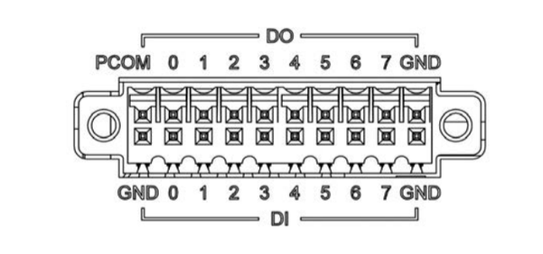
DGND is isolated The digital I/O section is isolated from the rest of the controller (2500Vdc). Do not connect DGND to the earth of the installation, nor to the ground of the Sofar EMS itself: that defeats the isolation which protects the controller.
The outputs are not relay contacts Unlike the relay outputs of the other models, the digital outputs of the Ultra are sink type. They only switch their terminal to DGND and they do not supply any voltage of their own. Every channel needs an external 5-30Vdc supply and a load in series.
Connecting a supply directly to an output without a load in series short circuits that supply through the output and destroys the channel.
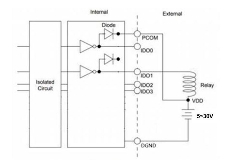
Wire each output as follows:
If you need to switch a higher voltage or current than the output is rated for, or if you need a potential free contact, use the digital output to switch an external relay that has the rating you need.
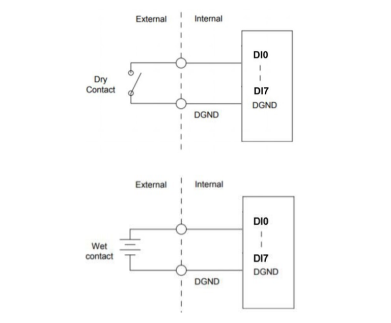
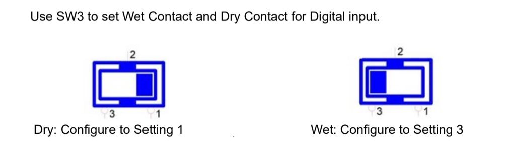
The inputs can be used as a dry contact or as a wet contact. The mode is selected with an internal switch S3, by default it is set as a wet contact.
| Mode | S3 state | How to wire it | Reads as activated when |
|---|---|---|---|
| Dry contact | 1 | A potential free contact between the input and DGND | the contact is closed |
| Wet contact | 3 | An external voltage between the input and DGND | 10-30Vdc is applied |
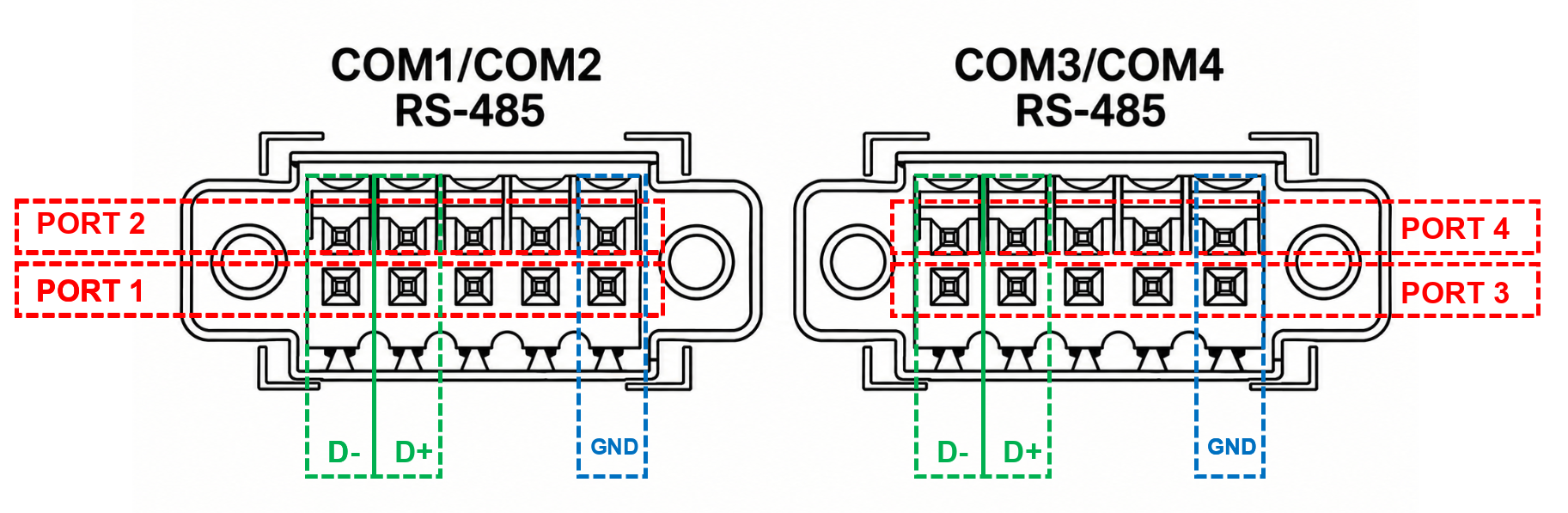
The Ultra has four serial ports, delivered configured as RS-485 and isolated to 2500Vdc. They sit on two terminal blocks with two ports each: COM1 and COM2 share the first block, COM3 and COM4 the second. In RS-485 mode a port uses three of its pins: D-, D+ and GND.
The following guidelines apply:
Different manufacturers use different naming conventions (A/B, +/-, D1/D0). Use this table to match your device's signals to the Sofar controller.
| Device | Sofar EMS model OM1 | Sofar EMS model IG8 | RS485-USB converter | RS485-Ethernet converter |
|---|---|---|---|---|
| RS485 A | RS485_POS | RS485 A | TX+ | |
| RS485 B | RS485_NEG | RS485 B | TX- | |
| RS GND | GND | Not available | G |
In case of many devices
Grounding shielded cables
Multiple ports Do not connect the same RS485 bus to multiple ports on the Sofar. This will introduce interference.
The termination resistors of the Ultra sit on internal switches on the mainboard and are switched off by default. Because reaching them means opening the enclosure, install a 120Ω termination resistor at both ends of the daisy chain instead.
You MUST give each device on the RS485 bus a unique address.
Use lower addresses first (1, 2, ...), because the Sofar EMS will find them faster!
Stick with the factory default baud rate, parity and stop bits. The Sofar EMS will scan on those first.